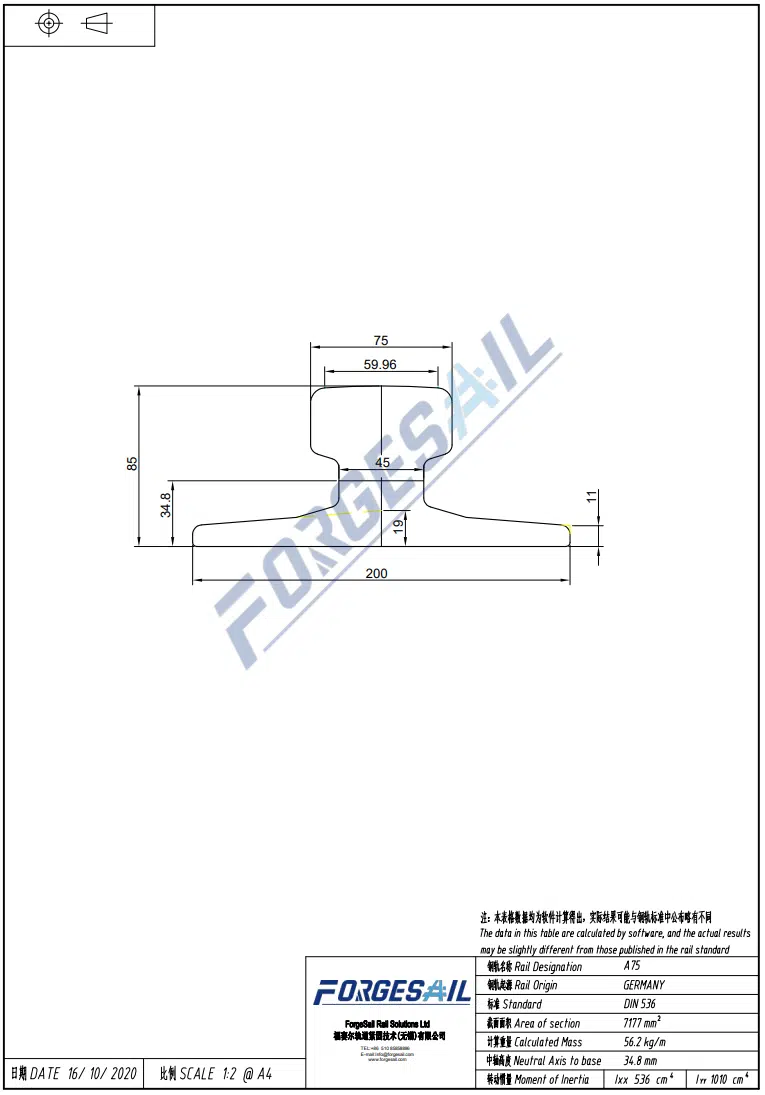




Crane rail force analysis is essential for safe overhead crane operation. Loads travel from the hook to the bridge, wheels, rail, and fastening system.
Overhead cranes endure vertical, longitudinal, and lateral forces that vary with lifting, travel, wind, and temperature. Under dynamic conditions, the rail suffers impact and vibration from load changes, start-stop acceleration, and surface irregularities.
This guide examines the 7 critical loads in crane rail force analysis and the fastening system requirements for each one.
1. Vertical Wheel Load: The Core of Crane Rail Force Analysis
Vertical loads include the crane bridge weight U, trolley weight G0, and rated lifting capacity Q. They act directly on the running wheels and the rail.

When the exact trolley weight is unknown in early design, it can be estimated from crane characteristic curves: G0 = (25 + Q) / 5. For formal design, always use the manufacturer’s actual trolley weight.
Heavy wheel loads create a significant overturning moment on the rail. As the rail flexes like a wave under a passing crane, conventional rigid all-steel clips loosen.
Engineering solution: a vulcanized rubber nose acts as a heavy-duty spring, maintaining dynamic downward clamping force and absorbing vertical shock.

2. Rolling Friction: A Persistent Crane Rail Force Analysis Factor
Rolling resistance comes from local deformation at the wheel-rail contact. For steel-on-steel contact, the rolling friction coefficient f is typically 0.02 to 0.04.
Longitudinal rolling friction: F_R = (0.02–0.04)(U + G0 + Q).
Engineering solution: rail clips must balance longitudinal loads without fully locking the rail. Complete locking prevents thermal movement and leads to rail buckling.
3. Wind Resistance: The Outdoor Crane Rail Force Analysis Variable
For outdoor cranes such as port STS (ship-to-shore) cranes, wind load is a critical factor. The formula is F_W = C_W × q_W × A_W.
C_W is the wind-force coefficient, up to 1.6 for truss structures. q_W is the wind pressure and A_W is the total windward area.
Engineering solution: heavy wind loads transfer through the rail to the clips. High lateral restraint prevents rail side-slip during storms.

Wind load constitutes an important lateral load acting on crane rails. The following FEA plot illustrates wind‑drag coefficient distribution over the full quay‑crane structure for wind‑load calculation.
4. Inertial Forces: The Dynamic Crane Rail Force Analysis Component
During start-stop cycles, the crane’s mass produces an inertial force: F_a = (U + G0 + Q) × a / g, where a is the acceleration and g is gravitational acceleration.
Engineering solution: the fastening system must resist repeated dynamic loading without progressive loosening, a common failure mode for welded clips.
5. Inclination Gravity Component: A Crane Rail Force Analysis Detail
If the crane girder has a longitudinal inclination θ1, the wheel load generates a component along the rail: F_G = Pmax × sinθ1.
A height difference between the two girders creates a lateral inclination θ2: F_G = Pmax × sinθ2. This produces a severe lateral push against the rail.
Engineering solution: precise rail alignment and adequate clip lateral adjustment reduce inclination-driven loading.
6. Lateral Skewing Forces: The Most Dangerous Crane Rail Force Analysis Result
Lateral forces are the primary cause of crane skewing and severe wheel flange wear. They include lateral rolling friction, cross-direction wind, inertial forces, and lateral gravity components.
Lateral rolling friction: F_Rx = (0.02–0.04)(G0 + Q). Note: this simplified value covers trolley and load; bridge inertia is evaluated separately in full design.
Lateral wind resistance uses the lateral projection area A_x plus the girder projection A_l: F_W = C_W × q_W × (A_x + A_l).
Lateral resultant: F_X = F_Rx + F_W + F_a + Pmax × sinθ2.
Engineering solution: conventional cast-iron clips with rear installation gaps can fracture under heavy lateral impact. Hot-forged steel clips deliver superior yield strength and near-zero porosity, so they resist shear forces without cracking.

7. Thermal Expansion: The Overlooked Crane Rail Force Analysis Input
Steel rails expand and contract with temperature. A fully locked rail cannot move and will buckle under extreme temperature fluctuation.
Engineering solution: the fastening system must allow controlled thermal movement while maintaining lateral and vertical restraint. Adjustable rail clips provide this balance.

Conclusion
Crane rail force analysis shows that rails bear a complex combination of vertical, longitudinal, and lateral loads. Magnitudes depend on crane capacity, wind exposure, acceleration, and thermal range.
Track engineers must select a fastening system that handles multi-directional stress. By combining hot-forged steel with a vulcanized rubber nose, ForgeSail rail clips provide an adjustable, self-locking solution for heavy-duty port and industrial projects.
Contact ForgeSail’s engineering team for application-specific crane rail force analysis and fastening guidance.
References
- GB/T 3811-2008 — Crane Design Specification (Chinese national standard)
- FEM 1.001 — Rules for the design of hoisting appliances
- ISO 12488-1:2012 — Cranes, tolerances for wheels and travel and crane tracks
- Consumable and fastening supplier technical manuals